- Room for insight!
- 0404 324 034
- info@controlhub.com.au
Case Study, Upgrade of the mixing plant (PART 4)

Case Study, Upgrade of the mixing plant (PART 3)
22 July 2022Case Study, Upgrade of the mixing plant (PART 5)
6 August 2022
CASE STUDY_UPGRADE OF THE MIXING PLANT (PART 4)
Test Procedure
Testing will be done in stages from components to completed circuits then the whole system. During testing water will be pumped instead of the real products to avoid wastage if a fault arises. The plant will run on semi auto and then fully automated when satisfied.
Final and full testing will be done on a weekend
Equipment required
- Digital Multi-meter capable of measuring 220 V ac, 380 V ac ,0 -24 V dc , resistance from 0 – 500 ohms
- Current tester (Clamp meter) capable of reading up to 200 Amps
- Mega meter capable of measuring insulation resistance up to infinite
- PLC simulators / demos
Procedures
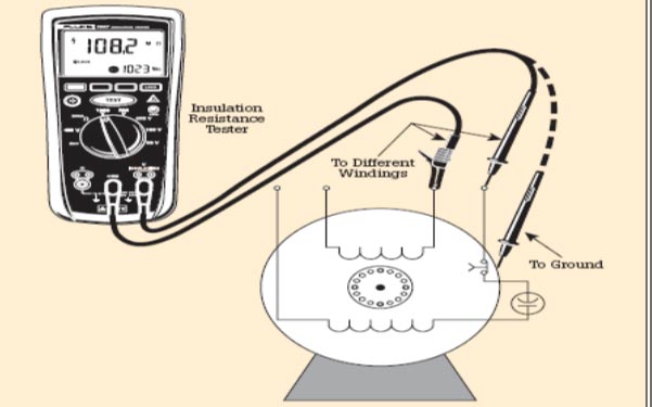
Cable insulation resistance test;
Testing wiring and cable installations: when testing wires or cables, they should be disconnected from panels and machinery and kept isolated. The wires and cables should be tested against each other and against ground (see diagram).
Test using a voltage about twice the cable’s rated voltage plus 1000 volts. Rated voltage is the maximum amount of voltage that the conductor can be exposed to for a prolonged amount of time, usually printed on the conductor. The higher the resistance, the better the installation. Keep a dated record of the measured values in a safe place to be used later to compare resistance valves as system ages.

Valve test
Make sure pressure is connected to valve actuator press the test button on the solenoid, the actuator should open the valve and changes color to green on the SCADA and goes back to red on releasing the button. Do same test procedure to all valves.
Valve PLC signal test
Valves appear blue on SCADA if they are closed and green when open. Open, PLC valve program via interface connected to PLC, disable any valve to be tested and then switch it to ON in the program, the valve should open and turn green on SCADA. This verifies that the PLC signal communicates with the valve. Do same test procedure to all valves.
Motor winding test
Set multi-meter to resistance range 200 ohms, open motor terminal box and measure resistance between each winding e.g. U1 and U2, V1 and V2,W1 and W2 the ohms readings of the three windings should the same or slightly different. Do same test procedure to all motors.
Motor Insulation resistance
When testing the insulation resistance of the stator coils, make sure the stator winding and phases are disconnected. Measure the insulation resistance between windings and windings to ground. As shown below
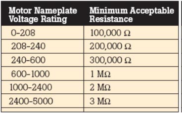
The following table lists recommended minimum resistance readings for various motor voltage ratings. In this case we use 240 to 600 V
Table 6 Recommended minimum resistance readings for motors
Motor circuits
- Switch on power to the panel. Now measure voltage with a multi-meter before and after every circuit breaker, the reading between phases should give 380 V and between phase and neutral or earth should give 220 V. This is to check if there is a missing phase.
- Test run all motors check functionality of stop and emergency buttons and those with star-delta starter check if star contactor kicks out within set time and delta gets in.
- Run motors and check direction of rotation for stirrers and they should turn clockwise, and pump motors should turn according to the direction shown on the pump, otherwise they should turn clockwise when standing behind fan cover.
- Start one motor without load e.g., if it’s a pump motor, decouple pump, using a clamp current tester measure current for motor phases, at NO load the motor should draw 1/3 of its rated current for example a motor rated 18Amps should draw 6Amps at NO load and the current reading on phases should be the same/balanced. Do same test procedure to all motors.
- Motors running on VSD just read currents from the VSD display
Flow meter and load-cell testing
With all calibrations done, pump water through flow meter to the empty mixing tank, the reading on the flow meter should tally with the tank level load-cell reading.
Mixer temperature probes
The mixer has two temperature probes inside each has its reading display, the readings should be the same or slightly different.
Interlocks
Force open the drain valve of mixer (Bottom valve) and then try to pump water into the mixer, the pump should fail to start and an interlock alert message appear on SCADA.
Visual status
The SCADA should always show status of pumps flows, etc. and be able to control the system
Final test
Run the mixing system on full automation pumping water to all possible destinations, this should be done on a weekend and most tanks be arranged to be free.
Major Components Used
Ball valves
Ball valves are to be used because of the following advantages:
Ball valves are excellent in chemical applications, readily available in the market, ease of operation, standard face-to-face dimensions, high flow capacity, high pressure/temperature capabilities, and ability to handle severe service chemicals, fairly easy to automate, easy to replace and have ability to provide fire safe protection
Specifications:
Ball valves shall be field repairable. Balls, seals, and seats shall be replaceable without welding or cutting. Threaded bonnets are not acceptable. 3-inch valves for gate pipe valves and 2-inch valves for other pipes and all valves shall be of anti-static design.
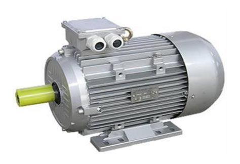
Three phase induction motors
Induction motors to be used their advantages:
They are ideal for centrifugal pumps and mixers, they are relatively inexpensive, simple and easy to use, highly reliable, and vibration free. Direction reversal is possible, and controls have pre-set speeds.
Flow meter
Magnetic flow meters are used. They are low pressure, volumetric, liquid flow measuring devices.
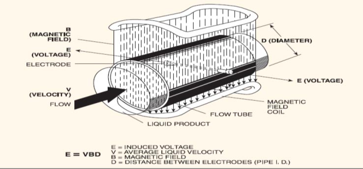
Advantages:
The low maintenance design with no moving parts, high accuracy, linear analogue outputs, insensitivity to Specific gravity, viscosity, pressure and temperature, and the ability to measure a wide range of difficult-to meter fluids (such as corrosives, slurries and sludge’s)
Specifications:
Model: RLC Type: Compression
Ranges: 100 kg – 50000kg
Nominal bridge resistance (ohms): 350/700
Material: Tool steel
Sealing: IP65
Solenoid
These are actuators which convert electrical energy into some form of mechanical motion. The one used is a 3-way normally closed - these have inlet, outlet, and exhaust ports. When not energized, the outlet port is connected to the exhaust port. When energized, the inlet is connected to the outlet port.
Advantages: they draw a very low current, water, and dust tight, corrosion resistant
Specification: Type: SHSNS, DC24V
Contactors
These switch on and off power to the motor and other high current circuits
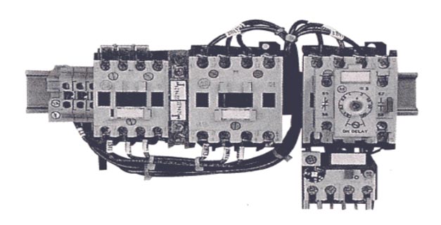
Specifications:
KW | COIL VOLTAGE(ac) | CONTACTS VOLTAGE(ac) | OVERLOAD RANGE (Amps) | Type | APPLICATION |
11 | 380V/50Hz | 380V/50Hz | 6 – 25 | Schneider | Mixer Stirrers |
15 | 400V/50Hz | 400V/50Hz | 11 – 35 | Schneider | Pumps |
11 | 400/50Hz | 400/50Hz | 16 – 30 | Schneider | Transfer Pumps |
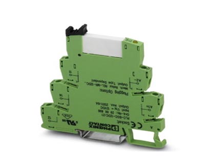
Relays
This manly link two different circuits for example the coil is activated by a 24V dc and its contacts switches 220 V ac.
Advantages
- Cost-effective plug-in relays instead of costly PLC relay cards
- Uses less space than conventional “ice cube” relays
- Fast and easy wiring using press-fit bridging
- Gold-plated contacts available for low-current signals
- Solid state relays for “no wear” high-frequency switching
- Integrated LED, reverse polarity, and kickback diodes
Applications: PLC input modules, PLC output modules, Actuators, Lamp loads, Sensors
Pumps
Centrifugal pumps are used. This type of pump is by far the most commonly type used in the chemical process industry.

Advantages:
These pumps offer low initial and upkeep costs. Traditionally these pumps have been limited to low-pressure-head applications, but modern pump designs have overcome this problem unless very high pressures are required. Good in the chemical process industry.
Specification:
Basically, pump selection is made on the flow rate and head requirement. With
other process considerations, such as material of the construction pumps for the corrosive chemical service or for the fluid with presence solids in the stream.
Advantages:
- They are compatible with Unity Pro software.
- Superior scan times and I/O throughput.
- Ability to handle interrupts, timed and I/O based.
- Handling of Fast task, as well as a Master task.
- Memory expansion through the expansion rack.
- Multiple communication interfaces embedded in the CPU.
- A user-friendly diagnostic and operation LCD display on the front panel of high-end models.
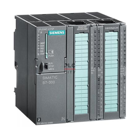
Specifications:
Type: Siemens S7-300
MODULE 1 | MODULE 2 | MODULE 3 | MODULE 4 | MODULE 5 | MODULE 6 | MODULE 7 |
PS 115/230 Vac |
CPU 314 Controller |
Ethernet 10/100 |
DI 24VDC |
DO 24VDC |
ANALOG IN |
ANALOG OUT |
Computer
Type: Compaq
Model | RAM | HARD DRIVE | PROCESSOR SPEED |
Pentium(R) 4 | 1GB | 250G | 3.8GHZ |
Table 9 Computer specification
Software
ITEM | TYPE | VEDA |
PLC | Siemens S7 | Siemens |
SCADA | In-touch 10.02 | Wonderware |
Computer | Windows XP sp3 | Microsoft windows |
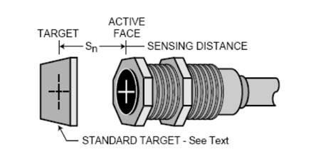
Sensors
IFM inductive sensors are used, proximity switches will operate electromechanical devices such as relays, contactors, solenoids, counters and valves without additional interface components:
Advantages:
- Used in the harsh environments.
- DC types provide an output compatible with solid state loads, including programmable controllers.
- Proximity switches offer reliable and long-lived operation in applications
- Sensing distance factory-adjusted to customer specification
- High frequency switching up to 2000 Hz
- Corrosion resistant stainless-steel housings,
- Over molded versions for underwater applications
- Metal sensing on products.
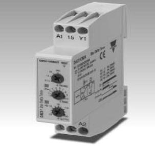
Timer
DAC51 timer is used
Advantages:
- Time range (Star to Delta): 0 to 30 ms
- Knob adjustable time setting
- Automatic start
- Repeatability: 0.2%
- Output: 5 A SPDT relay with neutral Centre position for mounting on DIN-rail.
- LED indication for relay status and power supply ON
Specifications:
Rated operational voltage through coil terminals A1 and A2, 380 VAC +10% -15%, 45 to 65 Hz
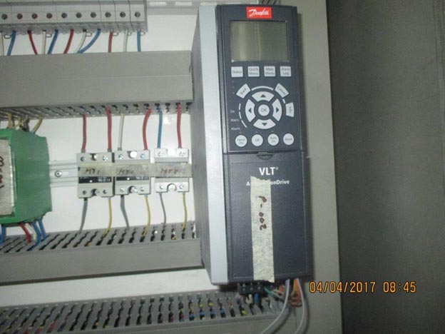
Variable Speed Drive (VSD)
Advantages:
• Variable speed drives allow you to match the speed of the motor-driven equipment to the process requirement. There is no other method of AC motor control that allows you to accomplish this.
• Energy saving e.g., at 80% Speed a motor uses 50% Energy when on a VSD
• Provide additional Protection: Over voltage, under voltage, over temperature, ground fault, control or microprocessor fault and provide indication of the fault condition on its display. The history of the previous three faults shall remain in memory for future review.
• Maintenance savings arise from running the motor at reduced speed, which lowers the load torque; lessens mechanical Stress on belts, bearings.
• Quieter operation at low load.
• Typical payback period is less than 2 years with reduced complains.
• Able to control speed of ac induction motor speeds
• Provide soft starting (reduce in rush demand on supply)
• Excellent input power factor due fixed DC bus voltage.
• Capability with multi-motor applications
Specification:
Product name: VLT5000 series
Type: Danfoss
Size: 15 kW
Input: AC3PH 380-480 V 50/60 HZ 30 A
Output: AC3PH 0-480V 0-400HZ 25 A