- Room for insight!
- 0404 324 034
- info@controlhub.com.au
Case Study, Upgrade of the mixing plant (PART 3)

Case Study, Upgrade of the mixing plant (PART 2)
7 July 2022
Case Study, Upgrade of the mixing plant (PART 4)
29 July 2022
CASE STUDY_UPGRADE OF THE MIXING PLANT (PART 3)
DETAILED DESIGN
Design procedure
The project building /installation will be done in parallel with the existing system where possible; this allows the plant to run smoothly while upgrading is taking place. A new panel housing plant motor control will be installed and wired aside not disturbing the existing one. The PLC, its software and wiring circuits will also be done without disturbing the running of the plant. The current plant does not have a PLC. The installation of valves, flow meter, load cells will be done during the weekends when the plant is not running, as these will be put on existing system pipes, mixers. In house Mechanical department will do the fitting and turning job like fitting valves, flow meter, load cells mounting pumps, motors etc.
All the project designing and electrical work, PLC programming will be done by in house Electrical department the author being in charge. On job training will be given to operators but supervisors will be trained separately before hand over of the project.
Locked Rotor Current calculation

kVA/hp corresponds to NEMA motor code letter which is F. From table 6-34 Electrical Machinery Fundamentals by Stephen J. Chapman, the range is 5 to 5.6. Hence the average is [(5+5.6)/2] = 5.3 kVA/hp.

The locked rotor current (LCR) is used to select the upstream circuit breaker. This is to make sure the circuit breaker can supply locked rotor current long enough to get the motor loads up to full speed and will trip if locked rotor current continues beyond allowable stall time. A circuit breaker at 250% rated current is enough to prevent tripping on start-up (NEC Protection table 430.52).
Upstream circuit breaker =250% of 38 A
= 95 A, (Circuit breaker size rounded off to 100A)
Wire/Conductor Calculations
Cable sizing is important to make sure wiring installation project is successful and meet requirements of electrical safety and regulations without disaster. The conductor size for a single motor must have a capacity of not less than 125% of the motor full load current rating (NEC article 430.22(A))
Therefore, the required wire capacity of the six motors = 125%38 = 47.5A
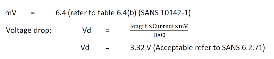
Cable size = 10mm2 (table 6.4(a): SANS 10142-1)
- Voltage drop calculations
SANS 10142 also stipulates that the voltage drop from the point of supply to the point of consumption (motor) shall not exceed 5% of the declared voltage. In this case the voltage drop shall not exceed 5% of 380 V = 19 V.
From panel to induction motor 23m
The required size of wires upstream of the 2 motors is found as per NEC article 430.24(a): conductors supplying several motors shall have a capacity at least equal to 125% of the full-load current of the largest motor plus the full load currents of all the motors supplied by the feeder.
Required feeder capacity = 38×125% + 5 = 52.5 A
Feeder cable size = 10mm2
Specifications for the Mixing Pump Motor
PUMP MOTOR 1 | |
Output power/Horsepower | 18.5kW/25Hp |
Supply Voltage | 380 V, 3-phase, 50 Hz |
FLA | 38 A |
Load Type | Delta |
RPM | 1490 |
Power Factor | 0.85 |
Code | F |
Table 1 Pump Motor specifications
- Specifications for the Circulation Pump Motor
PUMP MOTOR 2 | |
Output power/Horsepower | 2.5kW |
Supply Voltage | 380 V, 3-phase, 50 Hz |
FLA | 5 A |
Load Type | Delta |
RPM | 1428 |
Power Factor | 0.85 |
Code | F |
Table 2Pump Motor specifications
VSD motor control
All motors will be controlled by variable speed drives (VSD). The following points were put into consideration on the selection of VSD size and power rating:
- Is the load rating constant or variable?
- Will the system frequently start and stop or will operate continuously?
- Maximum torque and peak currents:
- Distance of cable from drive to motor
Sizing the VSD is not done according to horsepower ratings but according to the maximum current requirements at peak demand. The motor and the drive must be able to fulfill the demand of the process. Thus, a VSD of 44 A is selected which corresponds to 22 kW for the mixing pump.
At times de-rating of motors’ output when driven by VSD because of reduction in motor cooling i.e., fan mounted on the motor shaft varies with motor speed and therefore, circulates less air at reduced speed and the supply to the motor is not as clean as the grid supply. Harmonics originate from electronic switching by inverter and are responsible for additional losses and these additional losses cause the motors’ operating temperature to increase.
VSD Selection
Type: Danfoss AC Drive VLT5000 series
This type was chosen to keep uniformity with existing inverters which maintenance team is used to in the plant. The VSD is set according to its manual and entering the data from the motor name plate i.e., full load current rating, voltage rating, kW’s, speed (rpm) and locked rotor current and time.
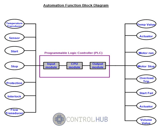
Programmable Logic Controllers (PLC)
A PLC is a digital computer used for the automation of industrial processes. Unlike general-purpose computers, the PLC is designed for multiple inputs and outputs arrangements, extended temperature ranges, immunity to electrical noise and resistance to vibration and impact. Programs to control machine operation are stored in battery-backed or non-volatile memory. A PLC is an example of a real time system since the output results must be produced in response to input conditions within bounded time, to avoid unintended operation.
PLC selection
Since the plant is already using Siemens PLC, to keep the same standard on the type which the maintenance crew is familiar with, the Siemens was selected with the following specifications:
- Type: Siemens S7-314
Type | Terminal type | Coil or Input Voltage/Current | Configuration/Current | Minimum Current(mA) | Contact Material | Maximum Voltage | Minimum Voltage | |
PLC-S7-314 CPU |
Screw clamp |
24 VDC/9 mA |
|
10 |
AgSnO |
250 VAC/DC |
12 VAC/DC |
Table 3 PLC selection table
Energy Sources
A 380 V, 3-phase feeder panel already exist and a 24 V, 10 A single phase obtained from the 380 V feeder through a transformer and rectification to power the PLC and motor control circuits. The system shall include a main disconnector to de-energize the whole mixing system for maintenance and repairs. The switch must be lockable in the open position to allow safe maintenance and repair of the system as well as cleaning of the tanks.
Overload Relays
The system shall have overload relays for individual protection of the electric motors. This is set in the VSD, the full load current rating of each motor is used.
Motor Enclosure
In accordance with NEMA general purpose electrical enclosure type 4, is used. This is for enclosures’ that are used outdoor or indoor to provide protection against windblown dust and rain, splashing water, and horse directed water, undamaged by the formation of ice on the enclosure. This is because there is a lot of water splashing, liquids and dust from the raw materials
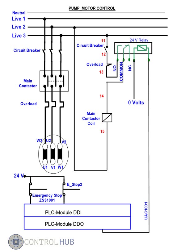
Detailed Power Wiring Diagrams
Below are power and control circuits designed according to their functions in the system: