- Room for insight!
- 0404 324 034
- info@controlhub.com.au
Case Study, Upgrade of the mixing plant (PART 2)

Case Study, Upgrade of the mixing plant (PART 1)
30 June 2022Case Study, Upgrade of the mixing plant (PART 3)
22 July 2022
CASE STUDY_UPGRADE OF THE MIXING PLANT (PART 2)
Components description
EFFECTS OF VSDs ON THE NETWORK
- They inject large harmonic currents (Radio Frequency Interference) back into the supply network. Leading to poor factor. The effects of the harmonics that are injected into the network include overheating of transformers, cables, motors, alternators, lights and capacitors; thus, and introducing faults on other equipment near the installed unit.
THREE PHASE ELECTRIC MOTOR PROTECTION
- Locked rotor protection
Relays protect motors against locked rotor conditions, which may occur on start-up or while running. The trip times will be a function of the difference between the remaining thermal capacity available to the motor and the thermal capacity already utilised at the time that the event occurs. Generally speaking, a time in the order of five to seven seconds can be expected. During this period, and because the given motor will attempt to supply both the necessary power and torque, it is possible to incur mechanical breakdowns as a result of over torque. The motor will however be protected. To circumvent possible mechanical breakdowns as a result of such incidents, some relays are fitted with a jam or running-stall protection feature.
- Overvoltage protection:
In the eventuality that the mains supply voltage is sensed to be greater than 115% of the rated supply voltage, a 10s trip delay will be initiated. Some relays in the range may permit the user more programming latitude both in respect to sensing threshold and trip delay.
- Overload protection:
Relays provide accurate overload protection for both cyclic and sustained overloading conditions. Cooling time constants are differentiated for an overloaded motor, which is still running, and one whose supply has already been disconnected by the protection relay as a result of an overload. New Elec relays calculate remaining thermal motor capacity as a result of sustained or cyclic overloading patterns. Selectors and specifiers should be aware that some competing products in this field only react to sustained overloading conditions and do not incorporate thermal imagery and / or memory in their design.
- Phase loss protection:
Otherwise known as single-phase protection, all new electrical relays are designed to disrupt the supply to the motor in the eventuality that a phase should be lost. The standard trip time is 5 seconds and will be effective even on motors running with no load. This trip time has been altered to 1 second on the MA, KA and KC range of relays.
TYPES OF VALVES
There are mainly three types of valves used in the plant for different operations namely.
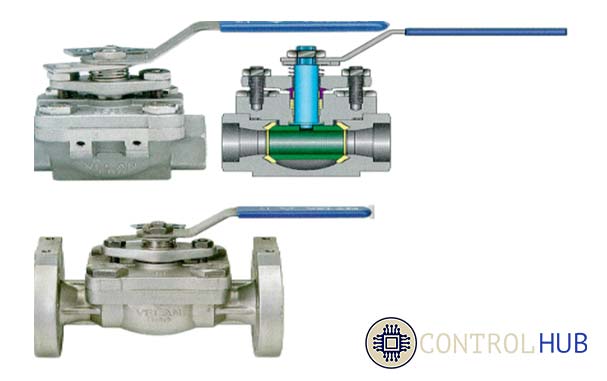
The ball valve
A ball with a hole through one diameter that can be rotated to align with the flow or block it. It provides quick tight shutoff, high capacity and require a quarter-turn to operate Can be actuated with pneumatic or electric actuators.
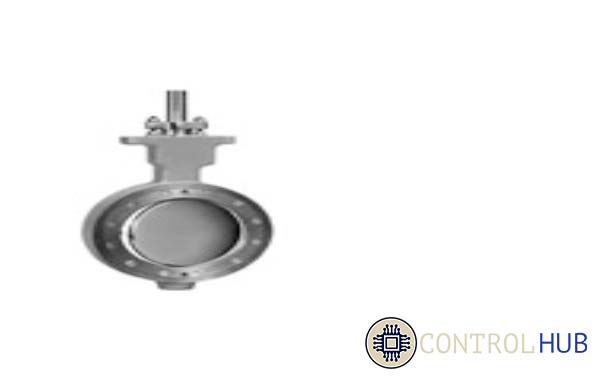
Butterfly Valve
Can be used for general and severe applications Liners help to provide tight shutoff, The most economical valves per comparable capacity and easily activated with pneumatic and electric actuators
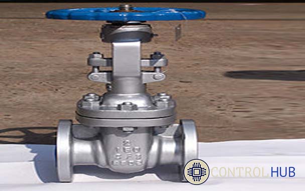
Gate Valve
A sliding disk slides up and down in and out of the fluid. Good for high pressure drops and high temperature applications where operation is infrequent. Manual operation multi-turn electric actuators are used.
The above valves are currently manually operated, and their operation will be automated by use of power operated actuator which may be the final element of an automatic control loop which automatically regulates the flow and level of the liquid raw material. Actuators may open or close the valve or allow intermediate positioning.
TYPES OF ACTUATORS
There are basically four types of actuators which are:
- Manual
These employ levers, gears or wheels to move the valve stem and are powered by hand. Manual actuators are inexpensive and are easy to operate but some valves are impossible to operate manually due to their location or hostile environment.
- Pneumatic
Air (or other gas) pressure is the power for the pneumatic valve operation. They are used on linear quarter-turn valves. Air pressure acts on the piston or bellows diaphragm creating linear force on valve stem. A pneumatic actuator maybe arranged to be spring-closed or spring-opened to provide movement.
- Hydraulic
It converts fluid pressure into motion and are used in quarter-turn valves. Fluid pressure acting on a piston provides linear thrust for the gate valve. A quarter –turn actuator produces torque to provide rotary motion to operate the quarter-turn. Hydraulic actuators may be provided with safe features to close or open valves under emergence circumstances. The pressure can be supplied by self-contained hydraulic pressure pumps.
- Electric
The electric actuator uses an electric motor to provide torque to operate a valve. They are quiet, non-toxic and energy efficient, but electricity must be present which the case is not always.
LIQUID LEVEL MEASUREMENT
The need for accurate and reliable level measurement systems is increased by the demands of advanced automated processing systems. By improving the accuracy of level measurement, the variability in mixing processes can be reduced, which, in turn, helps to improve product quality and reduce costs and wastes. Sight glass is the oldest and the simplest level measurement technology used in industrial environments. Sight glass is subject to many limitations as it is measured manually.
LOAD CELLS
Load cells are sensors that detect force i.e., mass, torque, etc. When force is applied to a load cell, it converts the force into an electrical signal. Load cells are also known as load transducers because they convert a load (force) into electrical signal. In various industries, it is becoming increasingly necessary to measure and computerize the weight (mass) of products in order to improve quality and productivity, and to reduce costs. The computerized data is often used for inspections and aggregate calculations. Load cells function as sensors that convert physical force into electrical signals. These electronic signals are then manipulated and finally the results are displayed on monitors for computers or other devices or printed and saved.
Load cells are used for quick and precise measurements. Compared with other sensors, load cells are relatively more affordable and have a longer life span.
FLOW METERS
Measuring the flow of liquids is a critical need in mixing plants. In some operations, the ability to conduct accurate flow measurements is so important that it can make the difference between making a profit or making a loss. In other cases, inaccurate flow measurements or failure to take measurements can cause serious (or even disastrous) results.
With most liquid flow measurement instruments, the flow rate is determined inferentially by measuring the liquid's velocity or the change in kinetic energy. Velocity depends on the pressure differential that is forcing the liquid through a pipe or conduit. Because the pipe's cross-sectional area is known and remains constant, the average velocity is an indication of the flow rate. The basic relationship for determining the liquid's flow rate in such cases is:
Q = V x A
where
Q = liquid flow through the pipe
V = average velocity of the flow
A = cross-sectional area of the pipe
Other factors that affect liquid flow rate include the liquid's viscosity and density, and the friction of the liquid in contact with the pipe.
Direct measurements of liquid flows can be made with positive-displacement flow meters. These units divide the liquid into specific increments and move it on. The total flow is an accumulation of the measured increments, which can be counted by mechanical or electronic techniques
Conceptual study and allocation of title
| 1) Employ more people to physical check status of processing every 30 minutes, double check measurements and feed the information into a computer for storage, and double check valve statuses before pumping, double check using a S.O.P (Sequence Operation Procedure). Many technicians to quickly trace fault in unmarked panels with no diagrams. | |
Advantages:
| Disadvantages:
|
| 2) Give the job to an outside contractor to come and build a new modern, automated plant | |
Advantages:
| Disadvantages:
|
| 3) Design a modern plant, automated which meet all user requirements | |
Advantages:
| Disadvantages:
|
The Decision-making matrix
| Criterion | Concept 1 | Concept 2 | Concept 3 | |||
| Score (%) | Weighted score | Score (%) | Weighted score | Score (%) | Weighted score | |
| Operational reliability | 30 | 20 | 100 | 100 | 100 | 100 |
| Maintainability | 50 | 50 | 100 | 60 | 100 | 80 |
| Initial cost | 100 | 80 | 80 | 25 | 80 | 60 |
| Long run cost | 50 | 25 | 60 | 45 | 100 | 90 |
| Development time | 100 | 100 | 60 | 25 | 100 | 80 |
| System Modification | 25 | 16 | 50 | 25 | 100 | 100 |
| Accuracy | 25 | 20 | 80 | 80 | 80 | 80 |
| Drawings availability | 0 | 0 | 25 | 20 | 100 | 100 |
| Efficiency | 0 | 0 | 100 | 100 | 100 | 100 |
| Graphic user interface/Process monitoring | 0 | 0 | 100 | 100 | 100 | 100 |
| Total weighted score | 311 | 580 | 890 | |||
Table 2 Decision making matrix
From the above options analyzed, the third option of designing a modern and automated plant, which meets all user requirements, is the highly rated concept, Concept 3 is now chosen as the best alternative to solve the background problems. The system is automated with high safety measures implemented to protect the equipment and the user. It also gives the technical department full control, makes it easier to modify and repair at minimum costs.
Therefore, the proposed project title is: ‘Upgrading and Automation of The Creamer Mixing Plant’
END OF PART 2